


CIF and its partner INTERELECTRONIC will be on Booth C05. We will be exposing our Vapor Phase Soldering System A...
Blog categories
Search in blog
Latest posts

Let's meet at INNOELECTRO 2024 !
Read more

Selective Soldering Technical Day on April 23, 2024
Read more
On April 23, 2024, CIF is organizing a technical day on the subject of board design for selective soldering. The day...

CIF at Global Industrie, interview with Philippe Albrieux
Read more
CIF at Global Industrie, interview with Philippe Albrieux Welcome to Majid Jlali, our production machine technician...

We will be present at GLOBAL INDUSTRIE 2024
Read more
Meet us at BOOTH 5V73 Come and see all our new products.

PROMOTION - 20% off your FT03.ADV reflow oven
Read more
From February 15th to March 31st 2024, Save € 667.00 on your FT03.ADVANCED oven.
Rapid prototyping: Mechanical or laser?
Re-designing boards in the wake of component shortages, design validation using laser or mechanical rapid prototyping?
Many manufacturers are having to redesign their boards, sometimes hastily, in order to unblock production following component shortages. Increasingly, customers are being forced to supply batches of components with equivalent or similar technical properties, even if the housings are different. This necessitates a re-design of the board, including prototyping. Given the time constraints on production, the demand for rapid prototyping is inevitably growing. However, the choice between different rapid prototyping techniques is not always obvious.
What is rapid prototyping, and what are its benefits?
It is essential to define the very concept of rapid prototyping before discussing it. Rapid prototyping is a computer-controlled manufacturing method used to produce prototypes or pre-production runs. The main feature of this technique is its speed of implementation, which enables a single piece of equipment to be used to go directly from a computer file to a final physical product. These are mainly CNCs (Computer Numerical Control or Machine à Commande Numérique) incorporating either machining technology for mechanical engraving, laser technology for laser engraving, or 3D printing technology for additive methods.

The additive method is currently very exclusive, and may not be suitable for re-designs, but is of interest for fundamental research or proof of concept. The latter type of rapid prototyping is not presented here, but feel free to discover Kelenn's equipment at www.cif.fr for more information.

There are other prototyping methods (such as chemical etching or screen printing with conductive inks), but these do not fall within the scope of rapid prototyping, as they systematically require tooling (photo-etched film for the chemical process, and a printing screen for the screen-printing method).
Similarly, although rapid prototyping alone cannot produce a multilayer PCB (Printed Circuit Board), it can be used to carry out certain stages. If you would like more information on the other steps involved in producing a multilayer PCB, please contact CIF: http: //www.cif.fr/.
The advantage of rapid prototyping is that it enables concepts and functional designs to be validated with great flexibility and speed of implementation. It can be more easily mastered in-house than traditional prototyping techniques. It is also simple to implement in a laboratory or design office, unlike traditional prototyping processes such as chemical etching.
Laser rapid prototyping is not always well known, and it's not always easy to identify the right solution for your needs, in both technical and budgetary terms.
Introducing mechanical rapid prototyping.
Mechanical rapid prototyping is the "traditional" method of this technique. It's the oldest and the most accessible in terms of budget. It uses a tool (milling cutter and drill) to engrave a substrate with the board's design. It's the most widely used technique today.
Engraving
Substrate and copper thicknesses are less of an issue with a mechanical spindle than with a laser. All that's required is to adapt the machining tool used. On power electronics applications, copper thicknesses can exceed 6000μm, so this is the preferred method.
The shape of the tool determines the shape of the tracks and the insulation:
- Conical engraving form (tool min. diam. 0.1 mm) Produces V-shaped "grooves".
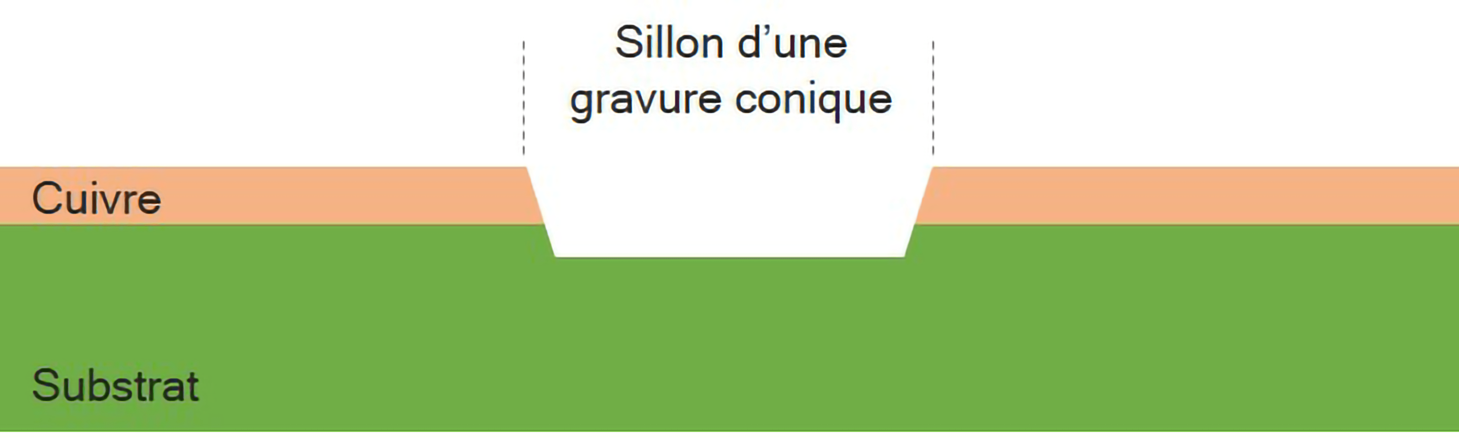 Diagram illustrating the cutting shape of a conical tool
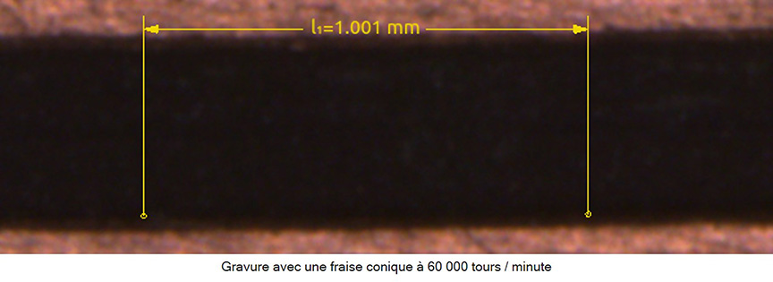
- Cylindrical engraving form (tool diam. min. 0.15 mm) Produces right-angle "grooves" - more fragile, requiring high rotation speeds (min. 60,000 rpm)
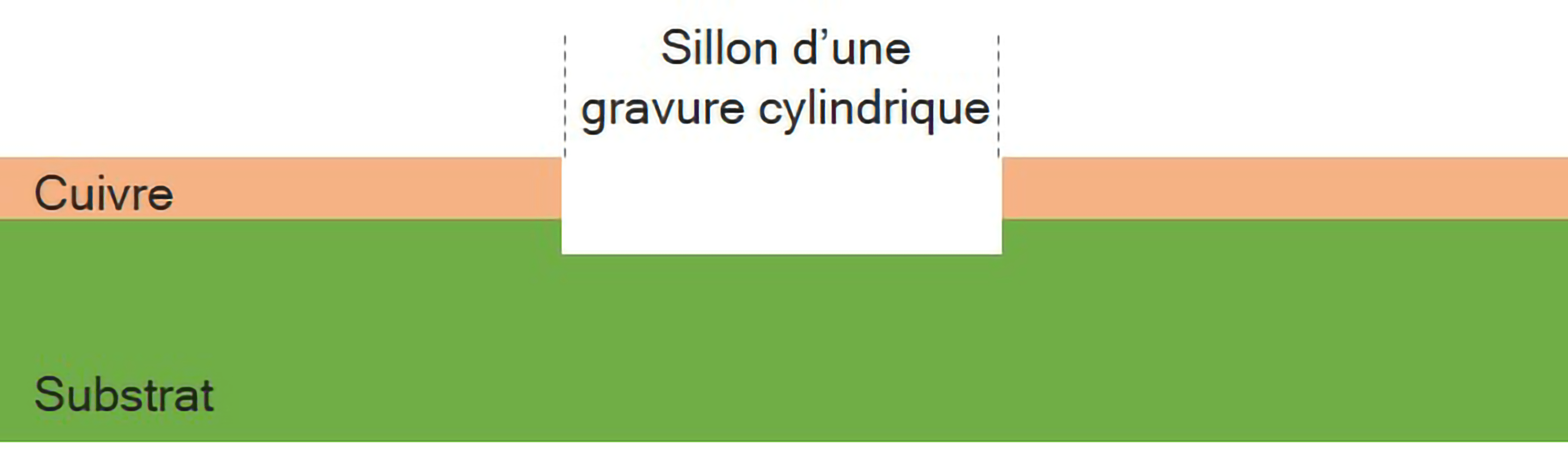 Diagram illustrating the shape of the cut of a cylindrical tool
It's worth noting, however, that the thinner the copper thickness, the easier it is to achieve high precision and engraving finesse.
The use of tools implies the need to stock the right tool for the right application. Generally, a maximum of 3 to 5 tools are required for customer applications, such as :
- 1 x Engraving cutter (for engraving tracks) 1
- x Routing cutter (for cutting PCB contours) 1
- to 3 drills for drilling holes (number of drills depending on the number of different diameters in the design).
Drilling
For traditional drilling, use the right tool for the diameter and material. The drilling tool used for FR4 will not be the same as for ceramic, for example. In addition, drill holes with diameters of less than 0.5mm wear more quickly and require higher rotation speeds. The drilling limits with a standard FR4 drill bit for mechanical drilling are around 0.2 mm in diameter, depending on the tools and materials used.
To guarantee consistent, high-quality results, you need to choose the right tool for the job. Tungsten carbide tools, in particular, are more resistant to abrasion than simple HSS tools, and ensure uniformity throughout the engraving process. A good-quality professional tool guarantees better results). Tool wear has the effect of altering the shape and/or dimensions of the tool, and can therefore degrade process quality over time. Finally, the precision of the tool itself is important to guarantee precision and repeatability.
Spindle selection
To produce "traditional" PCBs (single- or double-sided on FR4 copper substrate), a rotation speed of 20,000 rpm or more is sufficient. The advantage of "low-speed" spindles is generally their torque. This torque is particularly useful for drilling and routing, PCB surfacing or micro-machining of mechanical parts. These spindles are particularly well suited to engraving thicker copper, from 75microns to over 7000 μm. They are therefore perfectly suited to power electronics (thick copper and thick substrates) or Lightning (aluminum substrates).
The disadvantage of low rotation is a slightly cross-hatched etched edge, which modifies the impedance and resonance of the antenna, essential points in these designs. High-speed spindles from 60,000 rpm upwards will deliver a sharper cut and therefore better performance. These spindles are particularly suited to microwave applications. On the other hand, these very high-speed spindles deliver less torque.
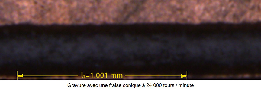
It should be noted that the spindle balancing grade and the quality of the tools used have a direct and essential impact on the quality and finesse of the engravings produced by the equipment.
Balancing is standardized to ISO 1940-1. By way of example, G2.5 balancing authorizes a permissible imbalance of the order of 1 gmm/Kg at 25,000 rpm, compared with only 0.45μ for grade G1 at the same speed, while it is of the order of 2.5 for grade G6.3. For precision machining, we therefore recommend G1 or lower (G0.4) balancing spindles. Note that the balancing standard implies precision proportional to speed (the higher the speed, the greater the precision for the same balancing grade).
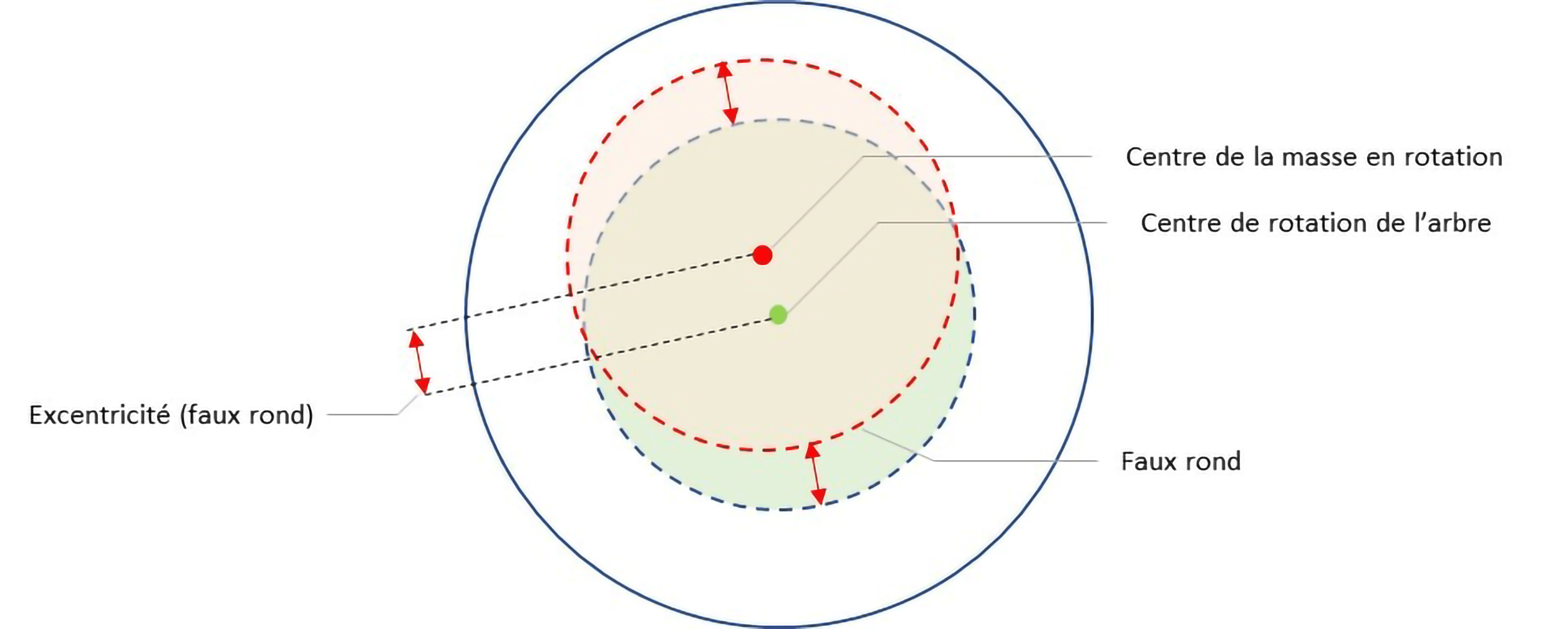 Diagram illustrating the eccentricity (runout) of a spindle
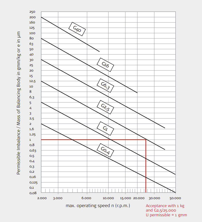
Representation of ISO 1940-1 standard
Flexibility
Mechanical rapid prototyping is also appreciated for its flexibility. It can be used for both engraving and drilling. This is not the case with lasers, where possible applications depend on the laser source, the materials to be machined and their thickness. This flexibility also applies to applications that are not necessarily limited to simple PCB production. Depending on the equipment, rapid prototyping systems can be used for other applications, such as front panels and various mechanical machining operations (aluminum, plastics, wood, etc.), which can be highly appreciated and make sense in laboratories dedicated to prototyping.
It should be noted, however, that some rapid prototyping equipment may be limited in certain applications by the torque of the spindles mounted (particularly for routing aluminum substrates) and by the Z-axis technology adopted, i.e. a controlled Z-axis or a nose-follower. In the latter case, 3D machining will be more limited. The useful height of the Z-axis and software for reading various types of file will also extend the range of possible applications.
Introducing laser rapid prototyping
Laser rapid prototyping is a more recent method. It uses a concentrated laser beam to vaporize material, with an impact point temperature that can exceed 3000°C. This technology requires no tools, but the choice of laser source is essential. Generally speaking, this technology delivers greater precision, but the budget is higher than for mechanical prototyping.
The materials to be processed are of crucial importance in the choice of laser system. Not only must the nature of the materials be determined, but also their thickness. It is also important to determine whether the laser is to be used solely for engraving and/or drilling. Based on these parameters, you'll then need to choose the wavelength, power and frequency or frequency range of the laser to be used. Don't hesitate to ask for advice on choosing the right laser source for your application. See also the table in the choice guide for double-sided copper-plated PCBs on FR4 substrates.
One of the undeniable advantages of laser machining over mechanical machining is its precision. The diameter of a milling cutter is at least 0.1 mm, while the diameter of a spot can be less than 0.15 μm. This makes it possible to perform micro-gravures and micro-holes. These features are highly appreciated for microwave applications, where the isolation between two tracks and the width of the tracks will therefore be more precise with the laser.
This precision and absence of tools means that designs can be produced with great finesse and resolution, without the machined material showing any physical signs of machining.
Laser machining will therefore enable very constant impedance and resonance of the circuits produced with very high finesse, ideal for microwave applications.
Example of electrical insulation on MEGTRON ® material for microwave applications using a UV laser.
In terms of performance, the standard minimum insulation between tracks can reach around 30 μm on polymer and around 10μm on ceramic. These data naturally depend on the laser sources used and customer parameters such as copper thicknesses.
It's worth noting that the thinner the copper thickness, the easier it is to achieve high engraving precision and finesse.
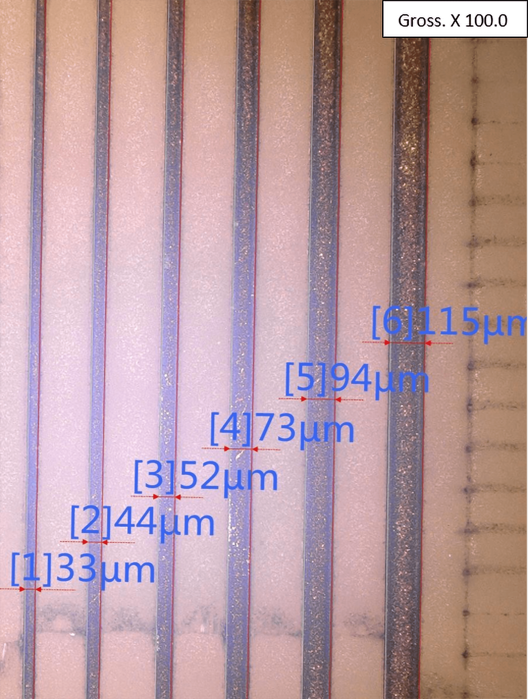
With regard to drilling, it should be noted that if the fineness is greater, the laser process will result in a slightly conical hole, rather than a perfectly cylindrical one. This must therefore be taken into account in the CAD and it must be ensured that these deformations are acceptable for the desired application.
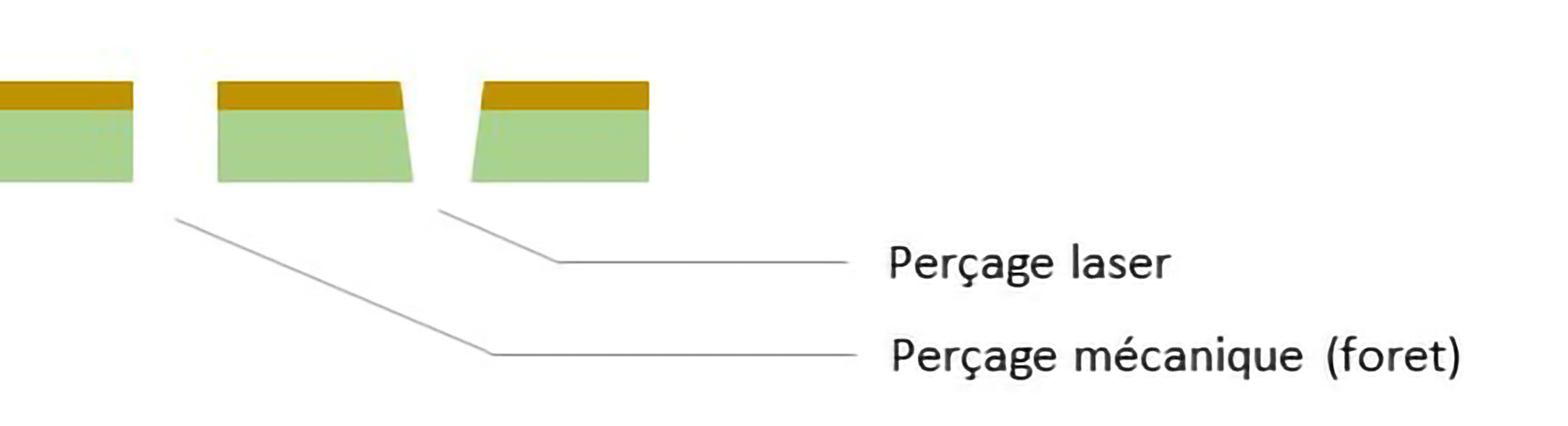
Diagram of the result of a cylindrical hole and a tapered hole, mechanical process versus laser.
 Top layer view MEGTRON ® material UV laser: average input Ø: 94.8 μm
 Bottom layer view UV laser - MEGTRON ® material: average exit Ø: 89 μm
Tests carried out on MEGTRON® material with a thickness of 0.3mm and a copper thickness of 17μm. The average difference between input and output diameters is 5.8 μm.
It should be noted that for laser drilling, the thinner the substrates, the easier they are to drill and the less conical deformation will be present.
Another advantage is the absence of vibrations and clearance constraints for the tool. This is important when routing boards (e.g. troubleshooting) or working with vibration-sensitive materials such as ceramics.
Laser prototyping also reduces the amount of swarf generated by machining vaporized material. It is also easier to extract.
Laser prototyping also eliminates the problem of tool wear, potentially improving the homogeneity of the result. What's more, laser prototyping eliminates the need to manage the logistics associated with physical tools.
Finally, depending on the material and laser source, the laser can also be used for engraving (PCB and component marking), text or even datamatrix.
And combined machines?
The main advantage of a combined machine is generally to use a laser source for PCB engraving and a mechanical spindle for drilling and routing, thus combining the best of both worlds.
While it may seem ideal on paper to have a laser head and a mechanical head on the same equipment, it's not.
One of the undeniable advantages is the reduced footprint (1 machine instead of 2). In some cases, the overall process time can be reduced, for example, by switching from a laser engraving application to a drilling application requiring no handling. But this depends on the machine's application and performance.
However, when it comes to productivity, two separate pieces of equipment can run simultaneously, even on different projects, resulting in a potentially higher OEE (Overall Equipment Effectiveness).
Often, for an equivalent budget for a combined machine, a mechanical machine will offer better overall performance.
It's also important to bear in mind that a clean working environment is essential for laser operation. Swarf or residues from previous operations can cause problems when using the laser, and excessive or repeated spindle vibrations can degrade the settings of the galvanometric heads (mirrors).
In summary
The choice mainly depends on the application. Here's a summary table for general cases.
|
Application |
Rapid Prototyping Generally Recommended* |
|
|
PCBs in Phenolic Materials (FR1 / FR2 / CEM1): |
Mechanical robot |
|
|
Traditional PCBs – FR4 / CEM3 Single or Double Sided: |
Mechanical robot |
|
|
Conventional Very Thin PCBs – FR4 Single or Double Sided |
Mechanical robot (Spindle speed ≥ 60 000 tr/min.) |
Laser robot |
|
High-Frequency Polyimide PCBs (Roger ® Type) |
Mechanical robot (Spindle speed ≥ 60 000 tr/min.) |
Laser robot |
|
PCBs on Aluminum Substrate (e.g., Lighting) |
Mechanical robot |
|
|
Flexible PCBs & Kaptons |
Mechanical robot (with a cutter head) |
Laser robot |
|
Ceramic |
Laser robot |
|
|
PCBs on Prepregnated Substrates |
Mechanical robot (Depends on the Technical Properties of the Prepregnated Material) |
|
*Recommendation taking into account the economic interest of the investment - applications may require additional tooling such as vacuum bases.
Indicative performance table for rapid prototyping types :
Data for the production of a double-sided copper-plated PCB on FR4 substrate. Criteria for selecting the solution, taking into account finesse, precision, electrical signature and mechanical stress on the substrate:
|
|
Milling |
Drilling |
Routing |
Laser source lifetime (min. estimate) |
|||
|
Mechanical process |
Spindle HF 24 000 RPM |
✔ |
✔✔ |
✔✔ |
|
||
|
Spindle HF ≥ 60 000 RPM |
✔✔✔ |
✔ |
✔ |
|
|||
|
Laser Process
|
Nanosecond |
Infrared |
✔✔ |
100 000 H |
|||
|
Nanosecond |
Green |
✔✔✔ |
✔✔ |
✔✔ |
10 000 H |
||
|
Nanosecond |
UV |
✔✔✔✔ |
✔ |
✔ |
10 000 H |
||
|
Picosecond |
Infrared |
✔
|
✔ |
✔ |
100 000 H |
||
|
Picosecond |
Green |
✔ |
✔ |
10 000 H |
|||
|
Picosecond |
UV |
✔ |
✔ |
10 000 H |
|||
|
Femtoseconde |
Infrared |
✔ |
✔ |
100 000 H |
|||
|
Femtoseconde |
Green |
✔ |
✔ |
10 000 H |
|||
|
Femtoseconde |
UV |
✔ |
✔ |
10 000 H |
|||
Selective soldering and rapid PCB prototyping. CIF at ioT Paris 2022
Posted in:
Press releases
Related posts
 Overview of SMD soldering technologies for prototypes and micro-series.
We offer you a comparison of the different technologies for soldering electronic boards, with the advantages and...
Read more
Hanwha: Modular systems and Industry 4.0
HANWHA, formerly SAMSUNG TECHWIN, provides SMT placement solutions combined with state-of-the-art service and...
Read more
The challenges of selective soldering and power electronics.
Power electronics, i.e. electronics applied to the management of high currents, is increasingly present in the...
Read more